On a digital substation, the SCD file is not a project appendix or a formal engineering deliverable. It is a formalized description of how the information model of the substation is supposed to be built: which devices belong to the project, what data they exchange, which data sets are defined, how MMS reports, GOOSE messages and Sampled Values streams are configured. It is the SCD file that should give the designer, the commissioning engineer and the customer one shared understanding of how the substation's information exchange is structured.
In practice, however, an inevitable question arises: does the actual device configuration really match the SCD file that was handed over to the customer?
This is the situation Tekvel engineers ran into during commissioning at one digital substation — and it is this real-world case that became the basis for this article.
The starting point
The job on site involved integrating devices into the control system. The task was to set up acquisition of telemetering and telesignaling over IEC 61850, using MMS.
The first stage of work on the substation had already been completed earlier by other contractors. The protection and SCADA devices had been configured, part of the digital infrastructure was already in operation, and the telecontrol system was being commissioned later — within the scope of our own work.
For the integration we were given an SCD file that was supposed to contain an up-to-date description of the substation's configuration.
But as soon as we connected to a few devices, it became clear that the actual configuration differed from what was described in the SCD.
That immediately raised a practical question: how do you quickly and reliably verify that every device on the substation matches the SCD that was handed over?
Why manual verification doesn't work
The most obvious approach is to connect to each device with a familiar tool — for example, OMICRON IEDScout or another viewer for the IEC 61850 model over MMS.
That approach does let you see the actual configuration of an IED: its logical devices, logical nodes, data sets, report control blocks and other elements of the IEC 61850 model.
But the manual approach has several major limitations.
First, every device has to be checked separately.
Second, the data read from each device has to be manually compared with what is described in the SCD.
Third, when there are many devices and even more data sets and reports, this kind of check very quickly turns into a labor-intensive and poorly scalable task.
Especially when you don't just need a yes/no verdict, but a piece of evidence: which elements match, which differ, where a data set is missing, where its content has been changed, where a Report Control Block, GOOSE Control Block or Sampled Values stream is configured differently, and so on.
In other words, a real substation needs not a one-off manual check, but automated reconciliation of the configuration described in the SCD with the actual configuration of the devices.
A side note: what would have changed with an IEC 61850 online monitoring system on site
It is worth noting separately that the task of checking the SCD against the actual device configuration is exactly the kind of thing a digital substation monitoring system is designed to do.
If an IEC 61850 online monitoring system had been deployed on site, conformance between device configuration and the current SCD would be checked automatically as part of continuous monitoring of the substation's digital infrastructure. Such a system would centrally connect to devices, monitor their configuration, detect changes, and produce deviation reports without the need for a separate visit to every device.
In our case, however, the substation was already in operation and no IEC 61850 online monitoring system was installed. We needed a different tool — one that could be used directly during commissioning for a one-off but full engineering check.
That is exactly the task Tekvel Magic was used for.
The solution: the verification module in Tekvel Magic
To solve this task we used Tekvel Magic — a multitool for working with digital substations and IEC 61850 communications.
The software includes a module for verifying conformance between an SCD file and the actual configuration of devices.
It works as follows:
- The SCD file is loaded into Tekvel Magic.
- The configuration of every IED is automatically extracted from it: - IP addressing; - DataSet composition; - MMS Report settings; - GOOSE settings; - Sampled Values settings; - the links between control blocks and data sets; - the contents of data sets at object and attribute level.
- The software then connects to each device over MMS and reads its actual IEC 61850 model.
- The configuration extracted from the SCD is automatically compared with the actual device configuration.
- A deviation report is produced as the result.
The full algorithm is easier to follow as a flow chart — from loading the SCD file to producing the final test report:
flowchart TB
    A["Load SCD/SCL file"]
    B["Extract list of IEDs<br/><i>Device names and IP addresses<br/>from the Communication section</i>"]
    C["Select devices to verify"]

    A --> B --> C --> D

    subgraph LOOP["For each selected IED"]
        direction TB
        D["Connect over MMS"]

        REF[("Reference (SCD)<br/><i>XML parsing</i>")]
        FACT[("Actual (IED)<br/><i>Read model over MMS</i>")]

        D --> REF
        D --> FACT

        DS["<b>DataSet check</b> (§ 6.2)<br/>• Presence of data sets<br/>• FCDA composition<br/>• Element order"]
        GS["<b>GOOSE check</b> (§ 6.3)<br/>• Presence of GoCBs<br/>• goID, datSet, confRev<br/>• MAC, APPID, VLAN"]
        SV["<b>SV check</b> (§ 6.4)<br/>• Presence of MSVCBs<br/>• smvID, datSet, confRev<br/>• smpRate, nofASDU<br/>• MAC, APPID"]
        RCB["<b>RCB check</b> (§ 6.5)<br/>• Presence of BRCB / URCB<br/>• Number of instances<br/>• rptID, datSet, confRev, intgPd<br/>• TrgOps, OptFlds"]

        REF --> DS
        REF --> GS
        REF --> SV
        REF --> RCB
        FACT --> DS
        FACT --> GS
        FACT --> SV
        FACT --> RCB

        DS --> V
        GS --> V
        SV --> V
        RCB --> V

        V["<b>Verdict per parameter</b><br/>✅ match / ⚠️ warning / ❌ deviation"]
        V --> DISC["Disconnect MMS"]
    end

    DISC -. "next IED" .-> D
    DISC ==> RPT["<b>Generate report</b>"]
    RPT --> CNT["<b>Report contents</b><br/>• List of devices and connection status<br/>• Per-IED results summary<br/>• Detail by DataSet, GOOSE, SV, RCB<br/>• Overall conclusion: PASSED / FAILED"]

    style A fill:#F3F3F3,stroke:#888
    style B fill:#F3F3F3,stroke:#888
    style C fill:#EDE7F6,stroke:#7E57C2,color:#311B92
    style D fill:#E0F2F1,stroke:#26A69A,color:#004D40
    style REF fill:#FAFAFA,stroke:#AAA
    style FACT fill:#FAFAFA,stroke:#AAA
    style DS fill:#E3F2FD,stroke:#42A5F5,color:#0D47A1
    style GS fill:#E3F2FD,stroke:#42A5F5,color:#0D47A1
    style SV fill:#E3F2FD,stroke:#42A5F5,color:#0D47A1
    style RCB fill:#E3F2FD,stroke:#42A5F5,color:#0D47A1
    style V fill:#FBE9E7,stroke:#E64A19,color:#BF360C
    style DISC fill:#E0F2F1,stroke:#26A69A,color:#004D40
    style RPT fill:#EDE7F6,stroke:#7E57C2,color:#311B92
    style CNT fill:#FAFAFA,stroke:#AAA
What it can detect
This approach makes it easy to spot deviations that are easy to miss or misinterpret in a manual check.
A comparison can reveal, for example, that:
- the contents of a data set in the device differ from what is described in the SCD;
- data sets defined in the project are missing from the device;
- the device contains additional data sets that are not in the SCD;
- MMS Report parameters differ from the project values;
- a report control block points to a different data set;
- MMS report parameters have been modified;
- the GOOSE configuration does not match the SCD;
- Sampled Values transmission parameters differ from the project values;
- some signals required for SCADA, telecontrol or dispatch are missing from the actual device configuration.
Crucially, the check shows not just the bare fact of a deviation, but exactly where in the configuration it occurs: which block has been modified, which parameters differ, which data is missing.
The commissioning engineer ends up with a concrete deviation report that can be used as the basis for the next steps.
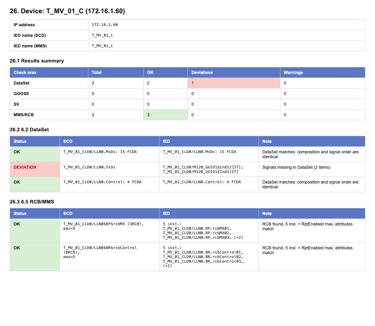
Results on a real substation
In this project, Tekvel Magic automatically compared the configuration of 76 devices with the SCD file.
The check showed that the SCD that had been handed over did not fully match the actual configuration of the devices on site.
Verification results:
Of the 76 devices checked:
- 62 devices matched the SCD;
- 14 devices contained deviations.
Statistics:
- total checks performed — 410;
- passed — 396;
- deviations identified — 14;
- warnings — 0.
The deviations identified were related to:
- missing signals in the data sets used by MMS reports;
- discrepancies in MMS report configuration parameters.
Final verification status: failed.
The full check on the substation — connecting to the devices, reading their MMS models, comparing them with the SCD and producing the protocol — took about 15 minutes and required just two actions from the commissioning engineer: load the SCD file and start the check.
Practical value during commissioning
For the commissioning engineer, this kind of tool is especially useful when a site is being handed over from one contractor to another, or when a control, telecontrol or SCADA system is being connected to already-configured devices.
In situations like that, the SCD file is often assumed to be "current by default", even though the actual configuration of the devices may have changed during the project. Verifying this manually is time-consuming and inconvenient: you have to connect to every IED, hunt for the right DataSets, reports, GOOSE and SV blocks, and then compare all of it with the project description.
Instead of manually opening every device, hunting for control blocks and comparing them with the SCD, the engineer gets an automatic report.
That makes it possible to quickly answer the key questions:
- Can the SCD that was handed over be used as an up-to-date source of data?
- Which devices actually differ from the project description?
- Which differences are critical for integration into the control system?
- Does the SCD, the device configuration or the higher-level system settings need to be corrected?
In practice that significantly cuts down the time spent looking for the cause of integration problems and reduces the amount of "manual" engineering work on site.
On top of that, this kind of report becomes a convenient technical basis for cooperation between everyone involved in the project — the customer, the designer, the previous contractor and the equipment vendor.
Value for the customer and for operations
This functionality matters not only for commissioning. It is also useful for protection, SCADA and energy dispatch specialists on the customer side.
A typical situation looks like this: the contractor finishes the work, hands over the documentation set and the SCD file, claiming that it matches the actual configuration of the substation.
But how do you quickly verify that this is actually true?
You can connect to a few devices and look at their configuration manually — but that only gives you a fragmentary picture. Or you can use the verification module in Tekvel Magic and automatically compare the SCD with the actual configuration of the devices.
A SCADA or dispatch engineer can quickly check, for example, how MMS reports are configured in the devices themselves and whether they match what is described in the handed-over SCD.
That matters because MMS is typically the protocol used to collect telesignaling, telemetering and other data for control, telecontrol and dispatch systems.
If the reports in a device are not configured the way the SCD says they are, the consequences can range from integration problems and incorrect data acquisition to a long search for the cause once commissioning has already started.
Why this matters for a digital substation
In conventional systems, many discrepancies could be caught by looking at wiring diagrams, terminal blocks and physical circuits.
On a digital substation, a significant share of the connections and settings only exists as IEC 61850 configuration.
If the file does not match the actual configuration of the devices, the operation and any further modernization of the substation become extremely problematic. This creates risks and problems when new systems are connected, when configurations are changed, when fault events are analyzed, when GOOSE messages, Sampled Values streams or MMS reports are checked, and during routine maintenance.
The relevance of the SCD file therefore becomes critical — it directly affects the manageability and supportability of the substation. If a substation has no up-to-date SCD, there is no reliable understanding of how the digital substation actually works.
That is why verifying the conformance of the SCD against the actual device configuration should be treated not as an extra check, but as a mandatory engineering procedure on a digital substation.
Tekvel Magic as a verification tool — outcome
In this case Tekvel Magic made it possible to automate a task that would otherwise have demanded a lot of effort and a lot of commissioning-engineer hours.
The logic stays simple and easy to follow:
- Load the available SCD file.
- Automatically extract the configuration of devices, DataSets and control blocks from it.
- Connect to the real devices over MMS.
- Read the actual configuration.
- Compare the project description against the real state.
- Produce a deviation report.
Quickly, conveniently and with evidence on hand.
Takeaway
This case is a clean illustration of the difference between continuous monitoring and a one-off engineering check.
If a digital substation has an IEC 61850 online monitoring system deployed, this kind of task can be solved automatically as part of the continuous monitoring of the digital infrastructure.
If a substation is already in operation and no IEC 61850 online monitoring system is in place, Tekvel Magic makes it possible to run that check as a stand-alone engineering procedure: connect to the devices, read the actual configuration, compare it against the SCD, and produce a deviation report.
For the commissioning engineer, that means a quick way to understand the real state of the substation.
For the customer — a way to verify that the SCD they were given really matches what is configured in the devices.
And for the operation of a digital substation — a tool that helps work from a base of technical evidence.
Real magic, if a thoroughly engineering kind.
Want to try it yourself? Download the demo version of Tekvel Magic and give it a try!